 lights.zip
La tentazione è forte: abbiamo comprato un'ottima scheda italiana Arduino e ora vogliamo cimentarci oltre il linguaggio Wiring, con programmi in assembler o in C (es. avr-libc).
Non c'è bisogno di comprare una scheda di sviluppo, perché è possibile usare il nostro Arduino come una scheda di sviluppo per programmi scritti in avr-libc, assembly, piuttosto che per gli sketch in linguaggio wiring, senza the need for external programmer hardware: our object code will be executed by the boot loader of micro Arduino, a simple and above all totally painless ...
Our config file is modified by adding options for avrdude (the programming software for the AVR micro) that will allow us to "upload" the object code on our Arduino.
below the config file for Arduino 2009 (ATmega168 and 16MHz clock). For later versions of the Arduino reference to the type of micro-and the frequency of the quartz.
  MCU name # MCU

      =   ATmega168

   # Processor frequency (in Hz)

   F_CPU         =         16000000

   # Target file name (without extension)

   TARGET         =     main

   # Object files directory
   #     To put object files in current directory, use a dot (.), do NOT make
   #     this an empty or blank macro!

   OBJDIR         =         .

   # List C source files  here. (C dependencies are automatically generated.)
   # The first one must be TARGET above defined, the other ones
   # must be separated by a space. Examples:
   # SRC = $(TARGET).c lcd.c i2c.

   SRC         =         $(    TARGET    )    .    c


   # List C++ source files here. (C dependencies are automatically generated.) spaced

   CPPSRC         =

   # List Assembler source files here.
   #     Make them always end in a capital .S.  Files ending in a lowercase .s
   #     will not be considered source files but generated files (assembler
   #     output from the compiler), and will be deleted upon "make clean"!
   #     Even though the DOS/Win* filesystem matches both .s and .S the same,
   #     it will preserve the spelling of the filenames, and gcc itself does
   #     care about how the name is spelled on its command-line.

   ASRC         =


   # List any extra directories to look for include  files here.
   #     Each directory must be seperated by a space.
   #     Use forward slashes for directory separators.
   #     For a directory that has spaces, enclose it in quotes.

   EXTRAINCDIRS         =

   # List any extra directories to look for libraries here.
   #     Each directory must be seperated by a space.
   #     Use forward slashes for directory separators.
   #     For a directory that has spaces, enclose it in quotes.

   EXTRALIBDIRS         =


  # Port programmer
  ... COMx # COM1 (serial port), LPT1 (parallel port)
  # Linux: / dev/ttyUSB0 or \u200b\u200b/ dev/ttyUSB1

  AVRDUDE_PORT         = / dev     /   ttyUSB0

  Type # programmer (stk500v1 for Arduino)

  AVRDUDE_PROGRAMMER     =   stk500v1

  speed serial # (19200bps)

  AVRDUDE_PORTSPEED         =         19200
AVRDUDE_PORT : specificare il device dove è collegato Arduino. Sotto Linux sarà generalmente /dev/ttyUSB0. Per conoscerlo lanciare da shell:
$ dmesg a simple program that turns five LEDs in succession. Through a button you can select the desired scrolling effect (SO) and through a second button you can change the flash time from 50ms to 500ms in 50ms increments. The scheme is shown below:
(diagram created with gEDA)
For correspondence ATmega168 pin / pin Arduino: 
(image created by Fritzing)
Method of resolution:
at regular time intervals (marked by a timer), it will change the combination of LED's (a combination we call frame), in a manner defined in the vector of its way.
Each element of this array contains a byte that encodes the start of the six LED, frame by frame. The convention is 1 -> LED ON, 0 -> LED off. The carrier will be so marked (in a time interval defined by a timer) in circulation.

time is used for a hardware timing (based on CTC with so Timer1 interrupt) so as to enable even better in practice as seen in previous posts and the management of the buttons are used the two interrupts INT0 and INT1. For the change of time is changed to run the register OCR1A to "step" of 50ms. The suid part with a time of 50ms, and then after 9 presses of the "Time" will reach the maximum value of 0.5 s, the tenth time the pressure starts from
50ms 50ms, 1 -> 100m, 2 -> , 150m, 3 -> 200m, 4 -> 200m, 5->250m, 6->300m, 7->350m, 8->400m, 9->500ms
Ecco il sorgente (main.c):
 (sintassi evidenziata creata al sito http://puzzleware.net/CodeHtmler/default.aspx)
* LIGHTS
* fp, 2010
*/
#
include
<avr/io.h>
# include <avr/interrupt.h>
#
include
  <avr/pgmspace.h>  #
 include
  <util/delay.h>


 #define    N              31249
     /* Numero del timer1 per avere un tempo max (31249=0.5s@fck=16MHz:256) */
   #define   NA
 3124       /* Numero del timer1 per avere uno step minimo (3124=50ms@fck=16MHz:256) */


 #define   NMODI          4          /* Numero di modi di funzionamento */
 #define   PORTDATALED  PORTB    /* Porta dove sono collegati i sei LED */      #define   PORTDDRLED   DDRB
 /* Registro direzione di PORTDATALED */          /* Prototipi delle routine dei various modes of operation * / void
   Shift_DX ();
 Shift_SX void ();    Shift_SX_DX void ();

 Out_In void ();

 / * Global Variables (qualifying static because they have to "live" even on function exit * /
 / * volatile and those shared with the interrupt service routine) * / static

 int frame = 0  ;
 / * Frame to be shown * / volatile


  static uint8_t mode = 0
;  / * Initial mode of operation (0 to nMode -1) * / static     uint8_t status = 0  ;  / * State variable (used for and how ShiftSXDX OnOff) * /
     / * sequences of frames for each mode * /    / * stored in flash memory (to save RAM) * / const
   uint8_t sx_dx [  6] = {PROGMEM   b00100000 0, 0

 b00010000,
 0  b00001000,
 b00000100 0, 0   b00000010,
  b00000001 0};   const uint8_t  out_in [  4] PROGMEM = {0   b00100001,   b00010010 0, 0   b00001100,   b00010010 0};
   / * initialize / configure the hwardware (direction pin I / O, timer, interrupt) * /     void init () {  PORTDDRLED  (On OCR1A)   OCR1A = NA;  / / load register OCR1A NA (minimum time)
 TIMSK1 = (1

 \u0026lt;\u0026lt;OCIE1A)
 / / Enable CTC interrupt on OCR1A   TCCR1B  * /}


   } / * TIMER1 interrupt service routine CTC: runs each (OCR1A +1) * 256 * Tck sec. * /
 ISR (TIMER1_COMPA_vect) {    switch (mode) {case
  0 : Shift_DX ();
 break;   homes
   1: Shift_SX ();   break
;   homes
 2: Shift_SX_DX ();


 break;
  homes   3 : Out_In ();


 break;}

}

    /* Routine servizio interrupt INT0 (pulsante variazione del tempo in step di 50ms ) */    ISR ( INT0_vect )  {
   OCR1A += NA;
 // incrementa di 50ms
 if
  (OCR1A >= N)
 // raggiunto il tempo max...

      OCR1A=NA;
 //...torna al tempo min.      _delay_ms(
 500
 );
 // debounce    }
         /* Routine servizio interrupt INT1 (pulsante variazione del modo fra o e NMODI) */
   ISR ( INT1_vect )  {
   modo++;            // passa al modo successivo         if
  (modo==NMODI)   // raggiunto il massimo modo...
      modo=  0  ;         // ...riparti dal modo 0
  _delay_ms(  500  );
 // debounce    }
     /* Modo 0: Scorre i LED verso destra */


 void
  Shift_DX()
 {
      if   (frame==
 6
 )
 // raggiunto l'estremo dx...          frame=
 0  ;     // ...vai al LED estremo sinistro       PORTDATALED = pgm_read_byte(&sx_dx[frame]);
 // leggi il frame e invialo the port   frame + +;
 / / pass to the next frame  }

 / * Mode 1: Scrolls the LED to the left * /


 void  Shift_SX ()  {

 if
 (frame == -   1)
 / / reached the extreme left ...   frame = 5  ;
 / / ... go to the far right LED    PORTDATALED pgm_read_byte = (& sx_dx [frame]);  / / read the frame and send it to port
  frame -;  / / go to the previous frame


} / * Mode 2: Scrolls  i LED da sinistra e poi da destra */
 void   Shift_SX_DX()  {

 if   (frame==  6  )   // raggiunto il LED estremo destro      {
     frame=  4  ;      // vai indietro di un LED
     stato=  1  ;
 //  stato 1: ora scorri i LED da dx a sx      }

 if
  (frame==-
 1  )   // raggiunto il LED estremo sinistro
     {      frame=
 1
 ;     // vai avanti di un LED        stato=  0  ;     // stato 0: ora scorri i LED da sx a dx
 }   PORTDATALED = pgm_read_byte (& sx_dx [frame]);  / / read the frame and send it to port

   switch
 (state) {  homes

 0
: frame + +;
 break
 ;  / / if you scroll from left to right, increases
  homes

 1: frame -;   break;  / / if you scroll from right to left, it decreases  }}

    / * Mode 3: Cycle through the LEDs from the outside and then back out * / void
   Out_In () {
  if
  (frame>=  4  )    // se siamo a un frame superiore a quello massimo         frame=  0
 ;
 // riparti dal primo frame      PORTDATALED = pgm_read_byte(&out_in[frame]);   // leggi il frame e invialo al port
   frame++;  }


 Creiamo una cartella (es. lights) nella quale ricopiamo i file:
 main.c
 config  makefile
   Portiamoci in questa directory e lanciamo      make all       e dunque "uploadiamo" il file oggetto su Arduino con:
  make program    If all goes well, in our shell will display the following output from avrdude:    make program ATmega168  avrdude-p-P / dev/ttyUSB0-b-c stk500v1 19200-F-U flash : w: main.hex

 avrdude: AVR device initialized and ready to accept Instructions

 Reading   an erase cycle will be performed
          To disable this feature, specify the -D option.
 avrdude: erasing chip  avrdude: reading input file "main.hex"  avrdude: input file main.hex auto detected as Intel Hex
 avrdude: writing flash (790 bytes):    Writing
 bytes avrdude: reading on-chip flash data: Reading
   varying the duty cycle remains unchanged, the wave generated not only the signal frequency, but also the implementation stage, this feature is therefore preferred for motor control.   In this mode the timer counts up from 0 and the maximum value N. Reached the maximum value N continues to count, but back to 0, and then recount again to N and so on, periodically.    So the time trend of the data in the register of timer1 (TCNT1) assumes a symmetrical triangular shape, rather than to ramp as fast mode, as illustrated in the following illustration:


 The front
 describes the rise of the wave count up (between 0 and N), while the count down is back (between N and 0).


 We note that the period of the signal generated (Ts) is twice the period T is obtained at N
 and that it should be taken into account in subsequent calculations, even for Ton.
You have up to two PWM channels: A (pin OC1A) and B (pin OC1B), then we can have two waveforms with different duty cycle, but of course both have the same period as the share the same timer.
The comparison is done on both sides wave (and not a single wave front as in fast mode) and what implies a maximum operating frequency is lower than that of a "fast".
Pin OC1A (or OC1B) is enabled the first comparison that occurs during the rising edge of reset and the next comparison, which occurs on the falling edge.
It is always possible to configure a waveform reversed, eliminating the pin on the comparison OC1x up and activating it on the falling edge.
The changeover takes place at the next clock pulse of the future equality between the value contained in the register TCNT1 and the value contained in the register OCR1A (OCR1B or whether we are using the second B channel) when
the maximum value of N was defined in Register ICR1(1)
. The value N, which thus establishes the resolution of Timer1, can take a value between 3 (minimum resolution of 2bit) and 65535 (maximum resolution of 16 bits).
Suppose we have a little problem typical for the control of a servant
timer1 to generate an ATmega168, OC1A pin on the back edge square wave signal (Ton = 2ms) with frequency of 50 Hz (T = 20ms) using as than the system clock (fc = 1MHz):
 V (OC1A)

 5V
 _ _  = 0V
 Ton Ton = 2ms 2ms
 ->
 For k = 1, 8, 64, 256, 1024, and Tc = 0.25 us (fc = 1MHz), substituting, we have:


 ----------
 N


 sostituendo, abbiamo
 NA=999


 Abbiamo tutti i dati per scrivere un possibile pseudocodice:


 Imposta PB1 come pin d'uscita;
 Imposta la modalità PWM a correzione di fase e di frequenza (e valore N definito in ICR1)
 Carica 9999 nel registro ICR1;
 Carica 999 nel registro OCR1A;
 Imposta forma d'onda non invertita;
 Imposta prescaler :1 (nessun prescaling, k=1)


 Come noto, l'istruzione di definizione del prescaler va sempre messa per ultima, in quanto dopo la sua esecuzione viene avviato il timer.

 Per quanto riguarda l'impostazione della modalità PWM a correzione di frequency and phase (with value defined in ICR1 N) just look at the datasheet dell'ATmega168 Table 15-4:
How is the number 8, for which you must activate the single bit WGM13 B register configuration timer1. In terms of education: 
TCCR1B when the register value OCR1A (for OC1A) and / or register OCR1B (for OC1B) equals that of the timer register TCNT1, through a combination of bits COM1A1/COM1A0 (to configure the waveform on pin OC1A) and COM1B1 / COM1B0 (to configure the waveform on pin OC1B) log TCCR1A: ----------------------------- -------------------------------------------------- ----
COM1A1/COM1B1 COM1A0/COM1B0 Description
------------------------------------- ----------------------------------------------
0 0 default: OC1A/OC1B pins are normally used as
pin I / O (not to pick PWM signals)
--------------------------------------------- --------------------------------------
0 1 pins are used OC1A/OC1B normally as pin I / O or if
set modes 9 or 11 (Table 15-4) switch status (toggle) 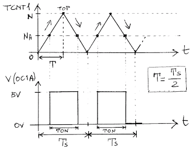 ------------------ -------------------------------------------------- ---------------
Clear OC1A/OC1B when equality is a  ------------------ -------------------------------------------------- ---------------
0 on the rising edge and active OC1A/OC1B
when equality occurs on the falling edge
(the waveform is NOT INVERTED)
--------------- -------------------------------------------------- ------------------
Enable OC1A/OC1B when equality is
1 1 on the rising edge and resets when OC1A/OC1B
equality is on the front of
descent (the waveform is inverted)
------------------------------------ -----------------------------------------------
So, wanting a waveform is not reversed, the only pin OC1A, the code will be: TCCR1A 9999 ;
// Ts=20ms @ fc=1MHz (:1)
OCR1A =
999
;
// Ton=2ms @ fc=1MHz (:1) TCCR1A with VMLAB, are shown below. The measureFinally, the measure of frequency, which confirms
Ton, as the difference between the times measured by two markers corresponds to the calculated 2ms:
Ts = 20ms (ie
fs
= 50Hz):
file contains the source main.c, makefile, and config files and project files for pwm2.prj VMLAB.
___________________
Note 1) E 'can be used alternatively register OCR1A. V. d / sheet


